
Tools I Used
Blender, Photoshop, Fritzing, Arduino
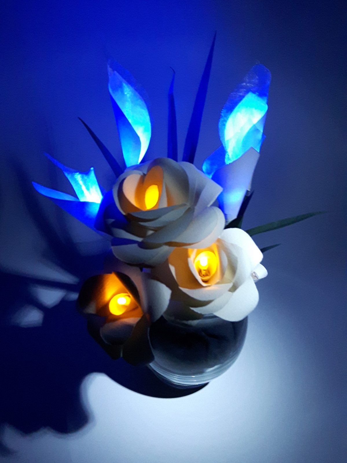
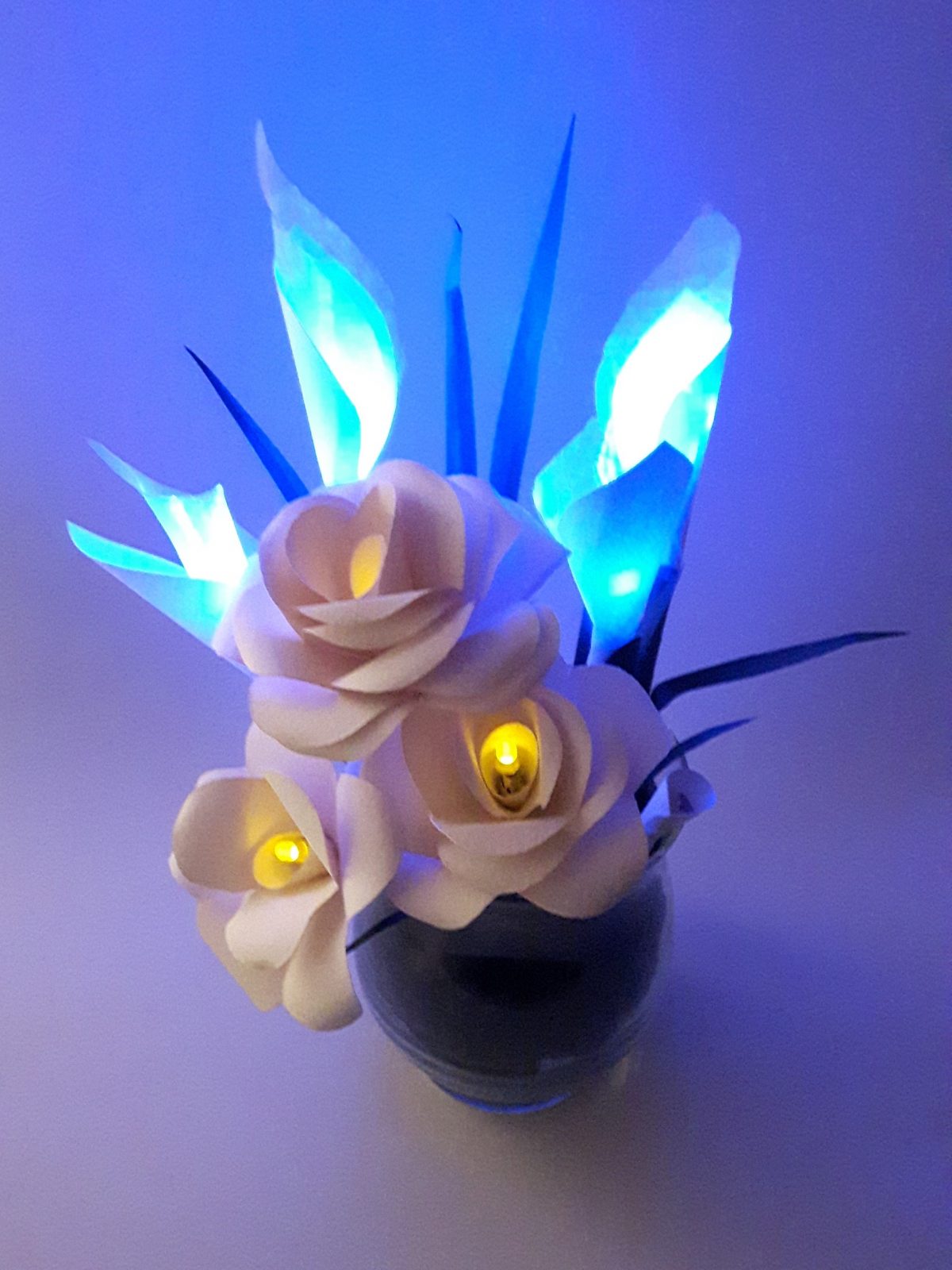
Moodflowers is a piece which explores the concept of the day and night cycle. The flowers react to the presence or absence of light in their surroundings, ‘waking up’ when there is sufficient light present, and ‘hibernating’ under dimmer lighting conditions. The colours used (yellow and blue) reflect the celestial bodies (the sun and moon). These robotic flowers respond to natural daylight and moonlight as well as light manipulated by humans.
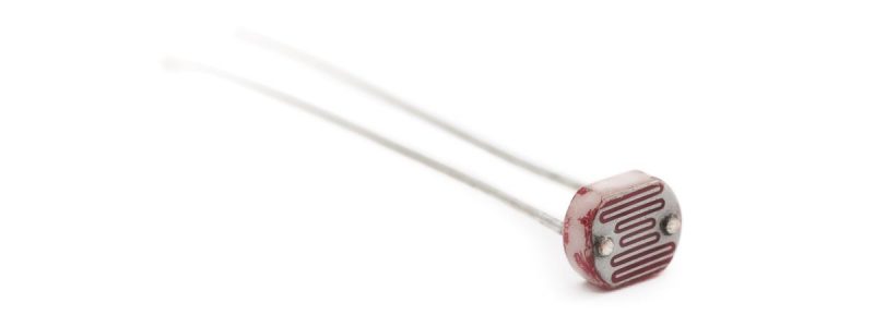
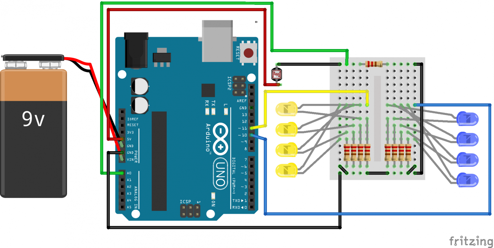
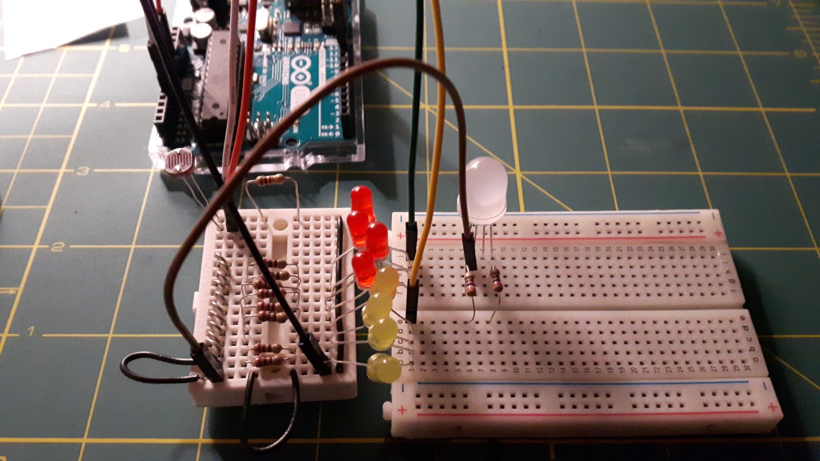
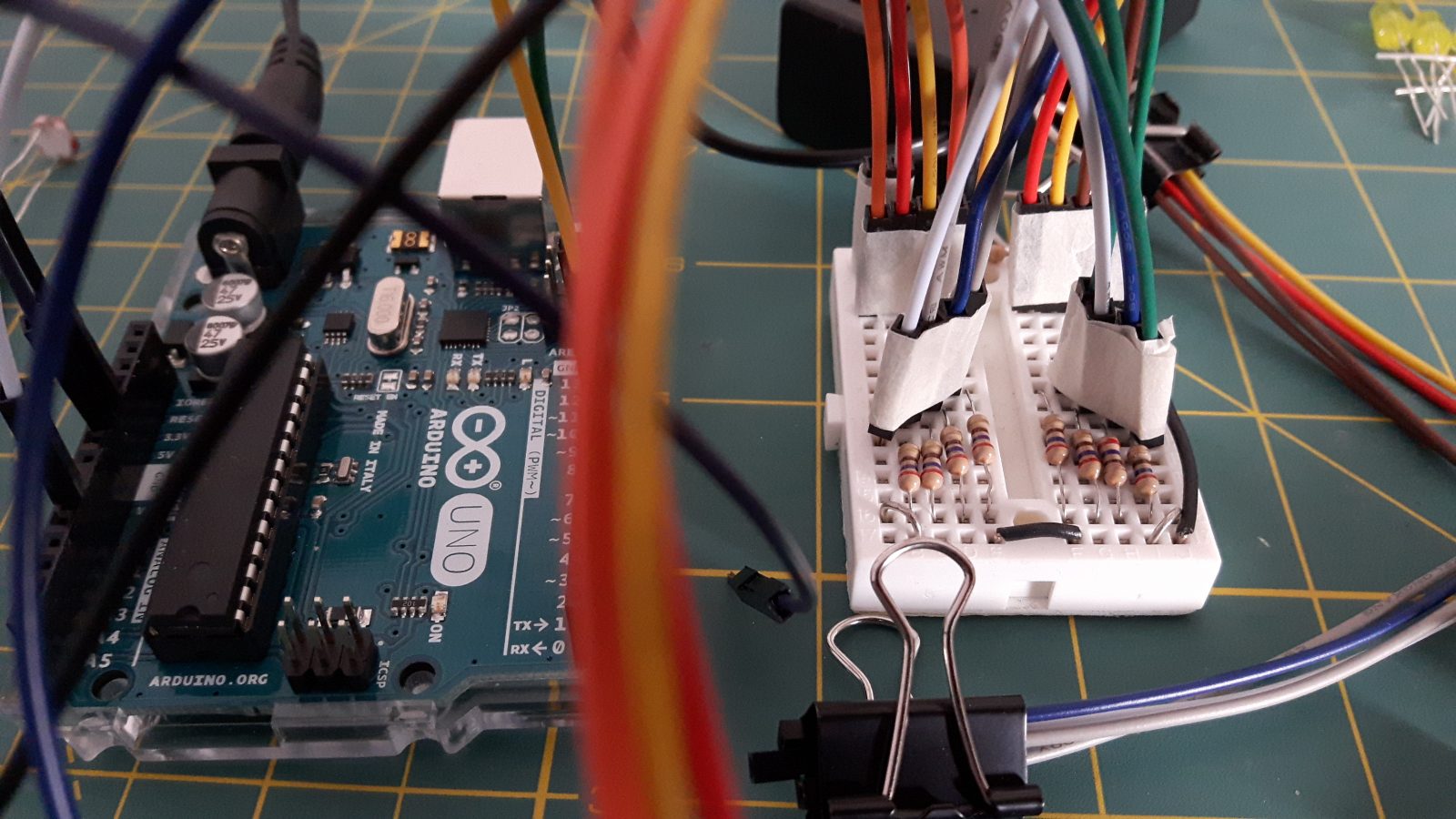
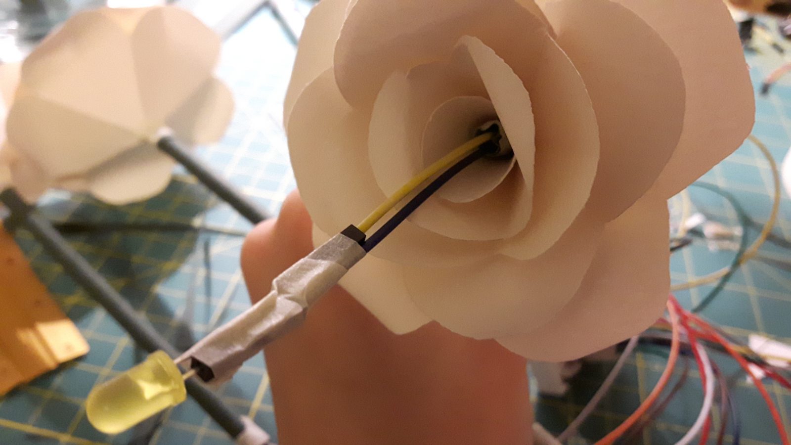
A photoresistor is used as an input to measure the current ambient light level. The Arduino Uno takes this information and translates it into a number between 0 and 255, corresponding to the output brightnesses supplied to the LEDs. This is done by mapping the analog input value from the analog pin (which ranges from 0 to 1023) and mapping it to a value between 0 and 255. The brighter the ambient lighting, the brighter the yellow LEDs and the dimmer the blue LEDs. Two pins (using pulse width modulation) are used as outputs. 4 LEDs are connected to each of the two pins, making a total of 8 LEDs (4 yellow and 4 blue).
Concept Art

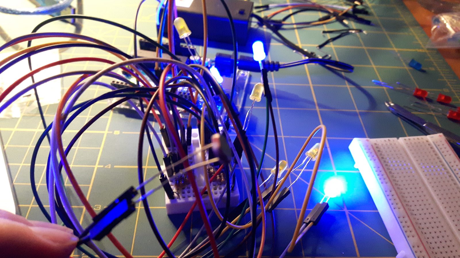
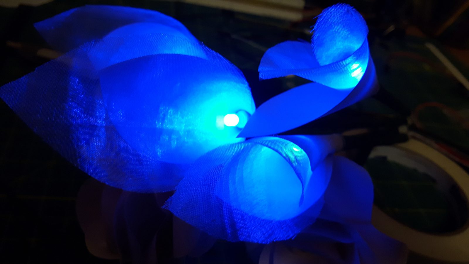
Low light
Blue flowers light up

Indoor light
All flowers light up moderately

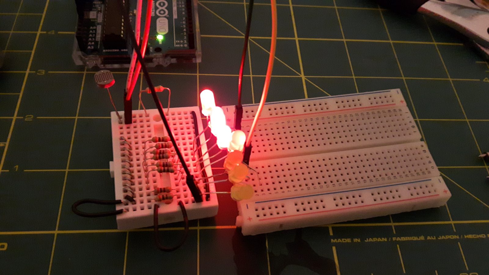
Daylight
Yellow flowers light up


Circuit Diagram
Breadboard view in Fritzing
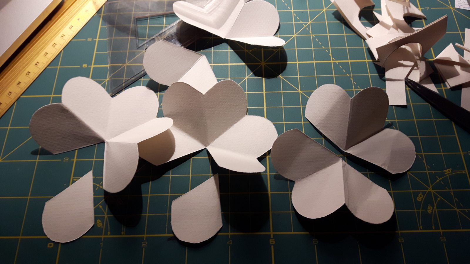
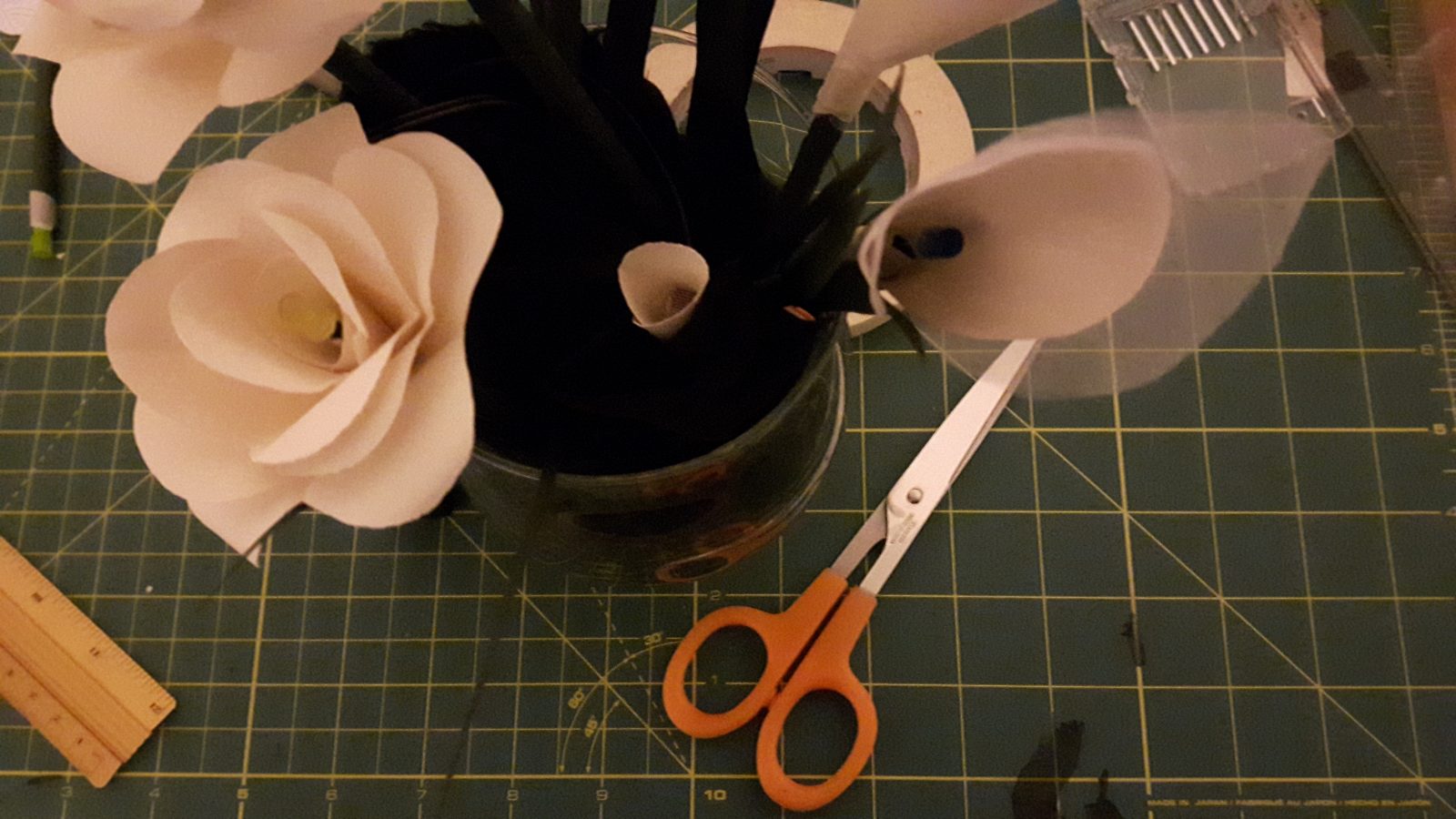
Final Images
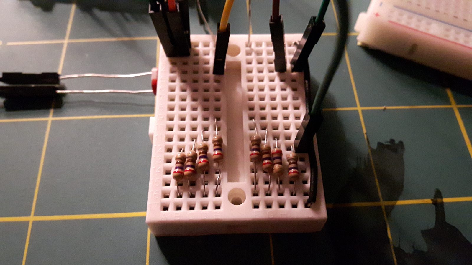
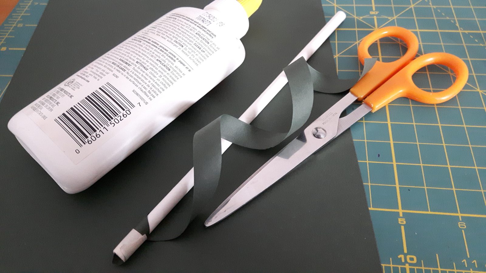
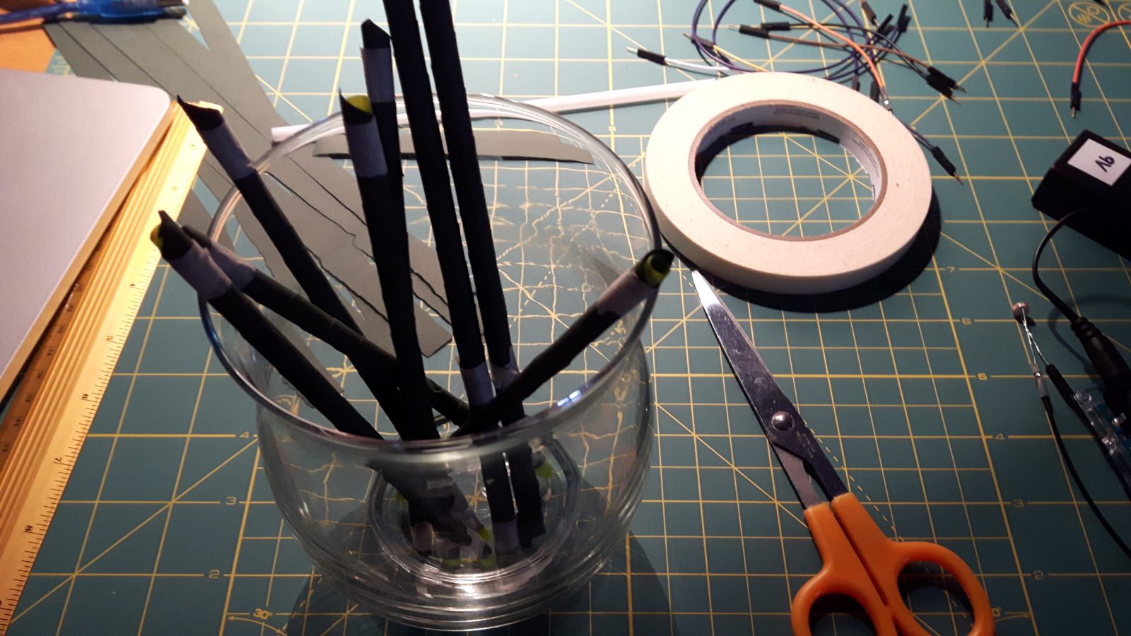
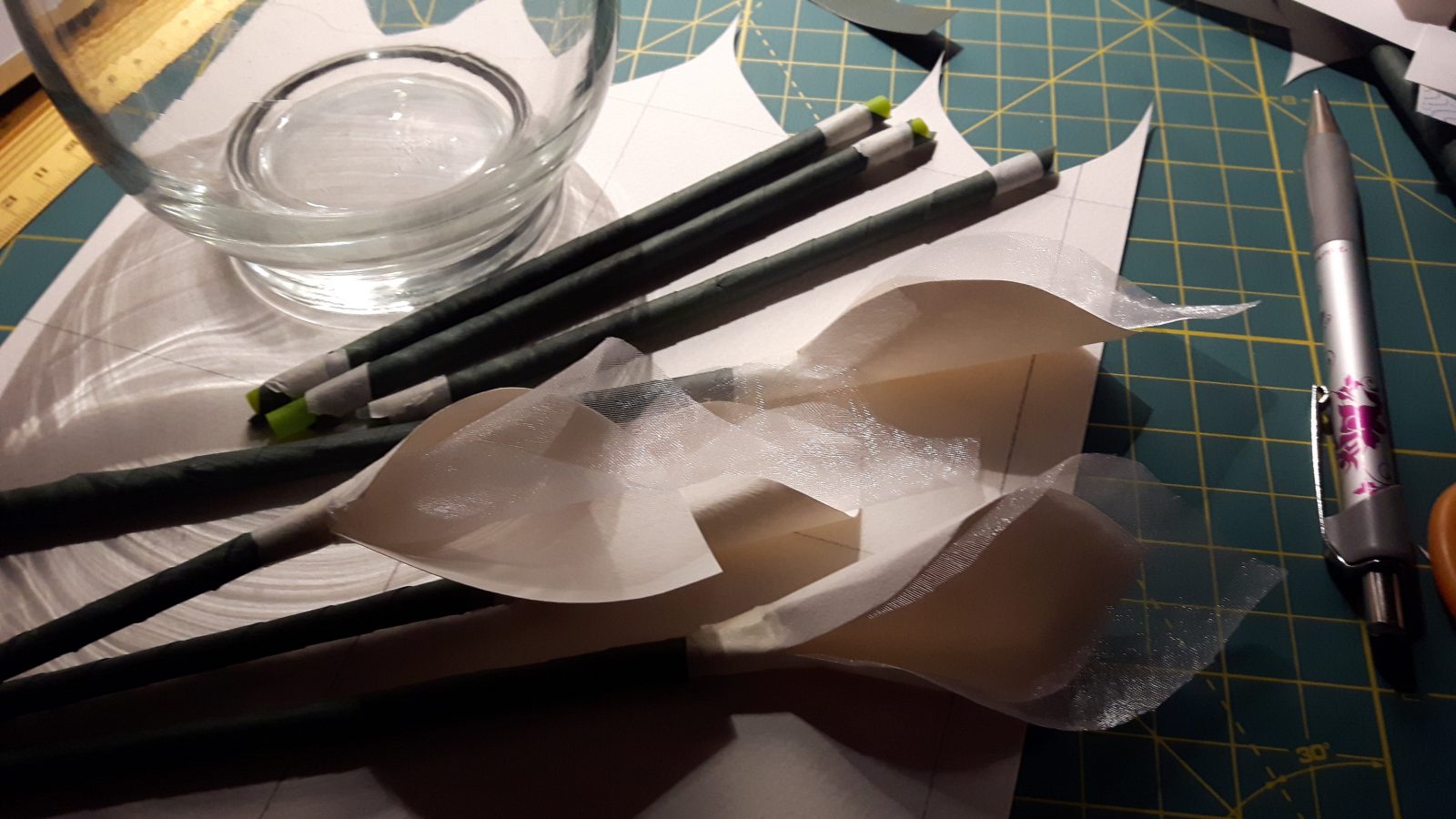
Process Images
Arduino Code
/*
  Moodflowers
  An Arduino project by Natalie Le Huenen
  References:
  Arduino mapping function:
  https://www.arduino.cc/reference/en/language/functions/math/map/
*/

//GLOBAL VARS
//input
int photocell = 0;  //analog in pin A0
//output
int bluepin = 10; //digital pin 10
int yellowpin = 11; //digital pin 11

//setting the initial brightness of LEDs to zero, this is modified based on the photocell's reading
int blue_brightness = 0;
int yellow_brightness = 0;

void setup() {
  //declaring the photocell pin as an input
  pinMode(photocell, INPUT);
  //declaring the blue and yellow LED pins as outputs
  pinMode(bluepin, OUTPUT);
  pinMode(yellowpin, OUTPUT);
  Serial.begin(9600);
  // to open the serial monitor, press the magnifying glass on the top right of the screen
}

void loop() {
  Serial.println(analogRead(photocell));  //print out the value that is read through the photoresistor
  //make the blue LED shine brighter the darker the environment is:
  analogWrite(bluepin, 255 - map(analogRead(photocell), 0, 1023, 0, 255));
  //make the yellow LED shine brighter the brighter the environment is
  analogWrite(yellowpin, map(analogRead(photocell), 0, 1023, 0, 255));
}